Start with line pull, not motor displacement
For a first screening, required drum torque equals line pull multiplied by effective drum radius: drum torque = line pull × effective drum radius. Effective radius is not always the bare-drum radius. It includes the drum core, half the rope diameter and rope already wound on the drum.
State rated and maximum pull separately. If the customer only knows the mass to be moved, that is useful input but not automatically the required line pull.
Rope layers change both pull and speed
As rope builds on the drum, the effective radius increases. With the same available drum torque, line pull decreases on outer layers; at the same drum rpm, rope speed increases. A statement such as “10 kN winch” is incomplete unless it identifies the rope layer or effective drum diameter.
Provide drum core diameter, rope diameter, usable drum width, required rope length and the layer on which rated pull must be achieved. If minimum pull matters near a full drum, use the outer-layer radius in the calculation.
Convert line speed into drum and motor speed
Required line speed determines drum speed, then the gearbox ratio sets motor speed. Use the effective radius that applies to the stated speed condition because line speed changes as the drum fills. Separate loaded speed, no-load return speed and any low-speed inching requirement.
The chosen motor must remain inside its verified speed range at every required operating point, not only during no-load recovery.
Match motor torque to differential pressure and flow
Motor output torque depends on displacement, pressure differential and mechanical efficiency. Useful differential pressure is inlet pressure minus return pressure and circuit losses; it is not automatically the pump relief setting. Calculate continuous and peak duty separately, then check the selected model data for pressure, starting behavior, speed and back-pressure limits.
Pressure and flow must be separate values with units. Record working pressure, peak pressure and available flow at working pressure. Confirm that the pump can provide the required pressure and flow at the same time.
Choose the motor structure for the duty
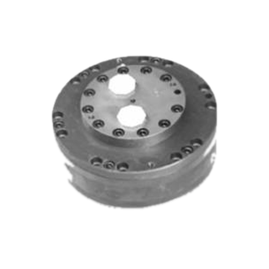
Radial piston motors are a common starting point for heavy winches that start under load, operate at very low speed or see frequent reversing and shock. Orbital motors can be practical for compact auxiliary winches and light-to-medium intermittent pulling where packaging and simplicity are priorities.
This is a starting framework, not a blanket rule. Final selection depends on the specific model’s starting torque, continuous torque, minimum stable speed, pressure, speed, case-drain arrangement and mechanical interface.
Treat motor, gearbox, brake and valve block as one system
The planetary gearbox converts motor speed and torque to the drum; the brake provides mechanical holding; and the valve block manages load control, relief, anti-cavitation, brake release and speed-change functions. These components must be checked against the same duty.
A brake is not a substitute for a correctly designed load-control circuit. For overrunning or suspended loads, the responsible machine designer must confirm the brake concept, counterbalance behavior, emergency condition and applicable safety requirements.
Information needed for a practical review
- Winch purpose and duty cycle
- Rated and maximum line pull, including rope layer
- Drum dimensions, rope diameter and rope capacity
- Loaded and no-load line speed
- Working pressure, peak pressure and available flow with units
- Return conditions, brake and valve functions
- Mounting space, shaft, ports, drawings or photographs
A reliable drive is selected backward from the rope and drum, not forward from a familiar motor code. Final model and safety-related functions must be confirmed for the actual machine before ordering.
Technical information is provided for preliminary selection. Confirm the selected model, installation and application requirements before ordering.