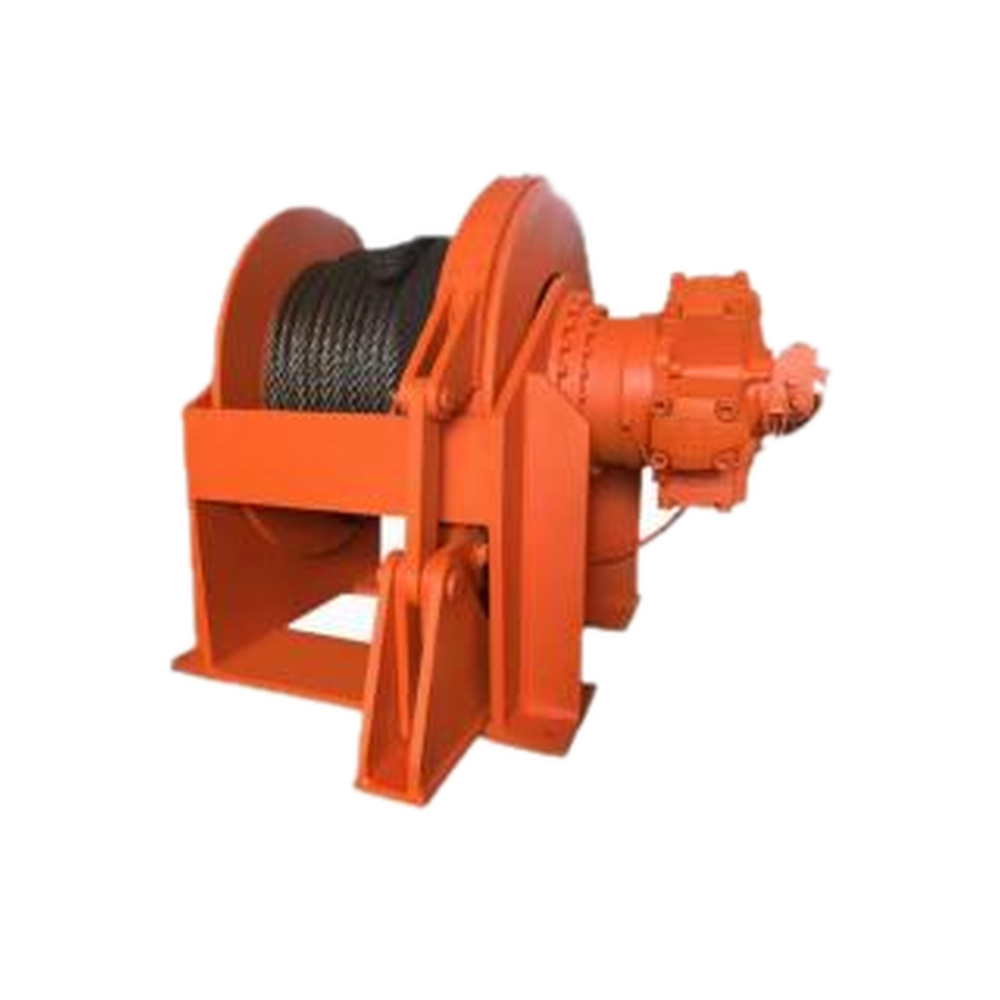
Hydraulic energy begins at the pump and valve
The pump supplies flow to the winch circuit. Flow is the main input for motor speed, while the pressure difference across the motor is related to available torque. A directional valve or integrated valve block starts, stops and reverses the winch. For controlled lowering or an overrunning load, the circuit can also use counterbalance, relief, make-up or braking functions.
A pump pressure setting is not automatically the pressure available at the motor, because hoses, valves and return lines create losses.
The hydraulic motor produces rotary torque
The motor converts hydraulic input into rotation. Displacement, pressure differential, mechanical efficiency and speed range determine whether a motor suits the duty. Low-speed high-torque motors are often considered where a winch must start a load smoothly, operate at low drum speed or work through a high reduction ratio.
The selected motor must also match the package mounting, shaft, port, case-drain and back-pressure conditions.
Planetary reduction changes speed into drum torque
A planetary gearbox reduces motor speed and increases torque delivered to the drum. The ratio cannot be selected only for maximum pull: it also sets line speed, acceleration and the flow demand seen by the hydraulic system. A very high reduction may create useful drum torque but make the winch too slow; a low reduction may give speed but require more motor torque or flow than the circuit can provide.
Motor and gearbox limits need to be checked together at continuous and peak duty.
The drum and rope turn torque into line pull
Drum torque becomes line pull through the effective drum radius. As rope layers build, the radius increases. This normally reduces line pull on outer layers and increases rope speed at the same drum rpm. Drum core diameter, flange diameter, rope diameter, usable width, rope capacity and the required working layer are therefore selection data, not cosmetic dimensions.
Fleet angle, rope entry and any level-wind arrangement also affect rope life and practical operation.
The brake and valves control holding and motion
A spring-applied, hydraulically released brake normally holds the drum when release pressure is removed. It is not the same component as a counterbalance valve. The brake provides mechanical holding; the counterbalance valve manages an overrunning load and controls hydraulic motion.
For lifting, lowering or suspended-load duty, the complete safety strategy must be defined by the machine designer and checked against applicable requirements. A winch intended only for horizontal pulling can use a different control arrangement.
Describe the whole duty when requesting a winch
- Purpose, rated and maximum line pull, and required rope layer
- Loaded and no-load line speed
- Rope and drum dimensions
- Available working and peak pressure plus available flow, each with units
- Duty cycle, environment, mounting envelope and control requirement
If figures are unknown, photographs, machine type and installation space are still useful. JST can then identify the missing values that matter before model selection.
Technical information is provided for preliminary selection. Confirm the selected model, installation and application requirements before ordering.