What the case drain does
Internal clearances allow a controlled amount of oil to reach the motor housing. The case drain returns that oil to tank or to a dedicated low-pressure return path. It also carries heat and contamination away from the housing. The acceptable case pressure and drain arrangement are model-specific, so the selected motor drawing and technical data remain the governing reference.
Warning signs to investigate
Oil appearing around a shaft seal, a housing that runs hotter than expected, unstable low-speed rotation or a sudden increase in drain flow can justify investigation. None of these symptoms proves that the motor alone is faulty. Return restriction, incorrect plumbing, contamination, overload and bearing or seal damage can produce similar evidence.
- Check for leakage at the shaft seal and housing joints.
- Compare operating temperature with the machine baseline.
- Listen for changes during starting, reversing and loaded operation.
- Record whether the symptom changes with oil temperature or duty cycle.
Inspect the return path before condemning the motor
Trace the drain line from the motor housing to its destination. Look for a closed valve, kinked hose, undersized fitting, restrictive manifold path or connection into a return line that develops pressure. A blocked or pressurized drain can raise case pressure even when the rotating group is still serviceable. Do not combine drain lines or change the tank connection without checking the motor and circuit requirements.
Measure and compare under repeatable conditions
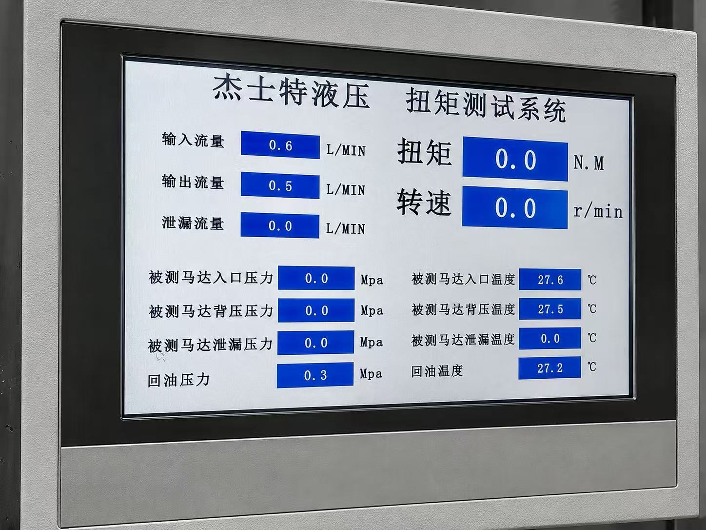
If the machine procedure permits measurement, record drain behavior at known oil temperature, inlet pressure, speed and load. Compare like-for-like operating points rather than one unreferenced reading. A rising trend across repeatable checks is more useful than a single value, but interpretation still depends on the specific motor data and the accuracy of the test arrangement.
Information to send for engineering review
- Motor series, model code and serial information
- Machine function, duty cycle and direction changes
- Inlet, return and case-drain connection diagram
- Observed temperature, leakage location and operating symptoms
- Available pressure, flow, speed and load information
- Photos of the ports, hoses, mounting and shaft interface
This information helps separate a motor condition from a circuit or installation problem before a replacement is selected.
Technical information is provided for preliminary selection. Confirm the selected model, installation and application requirements before ordering.