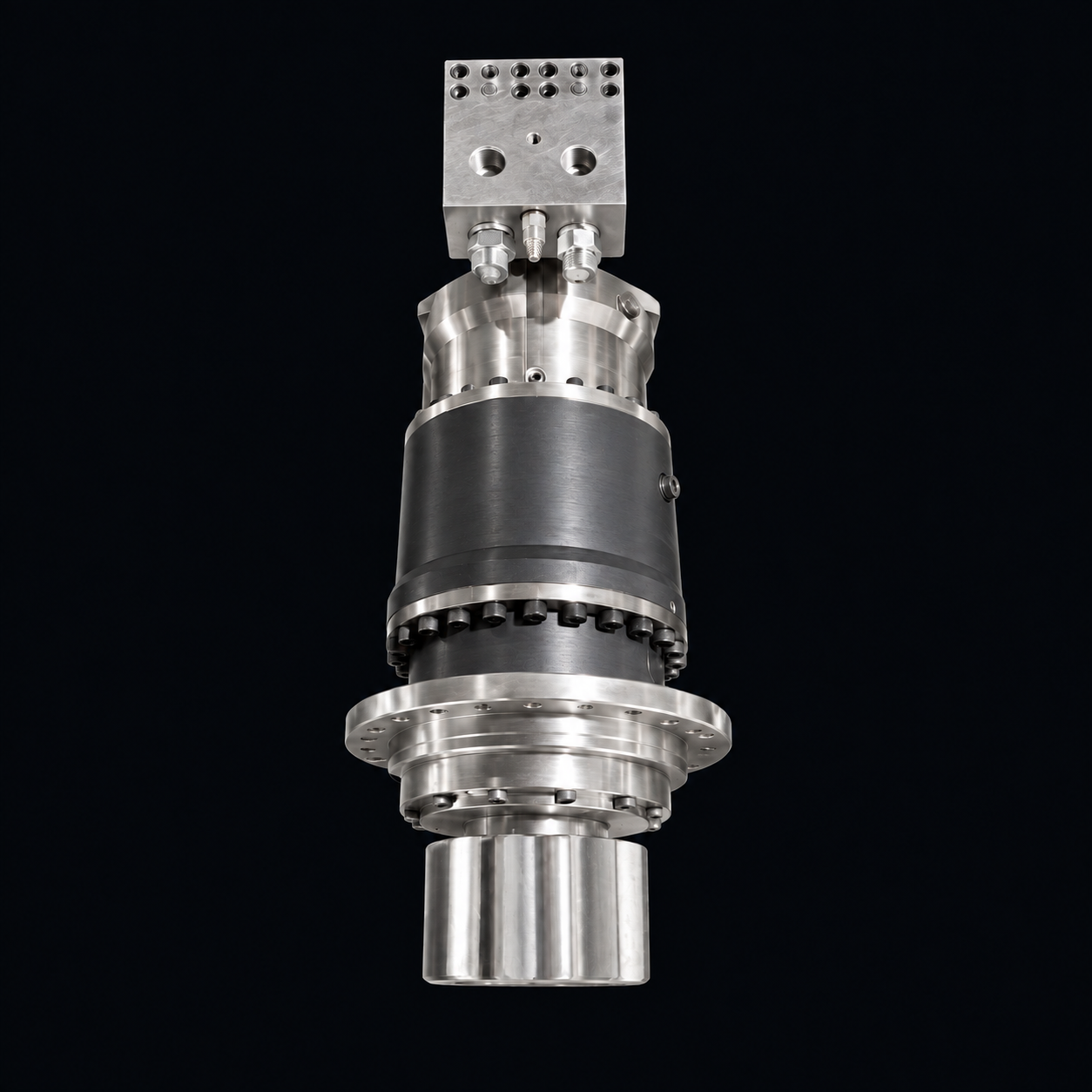
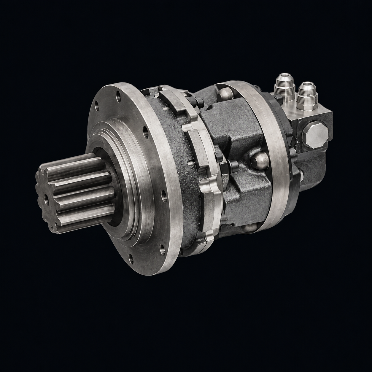
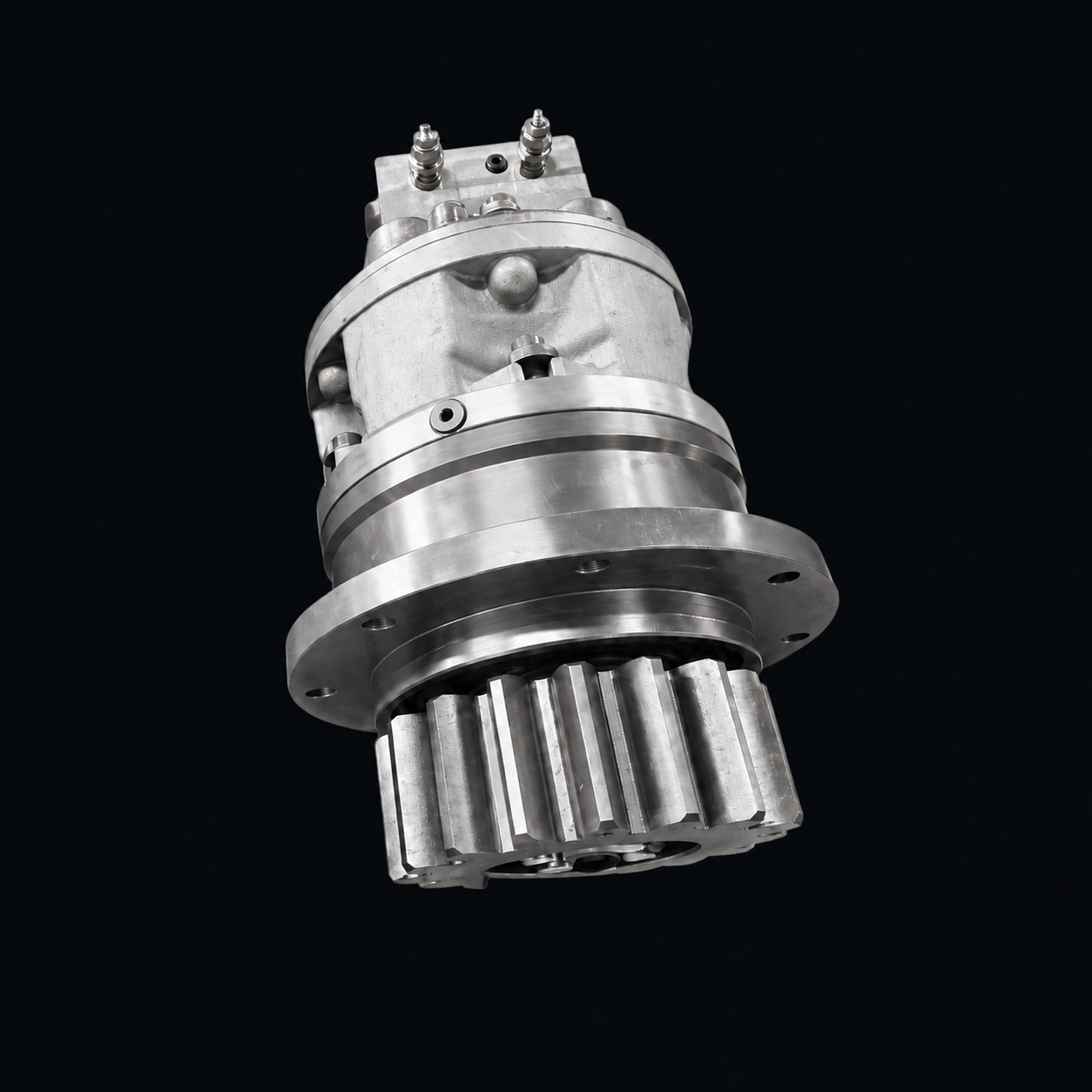
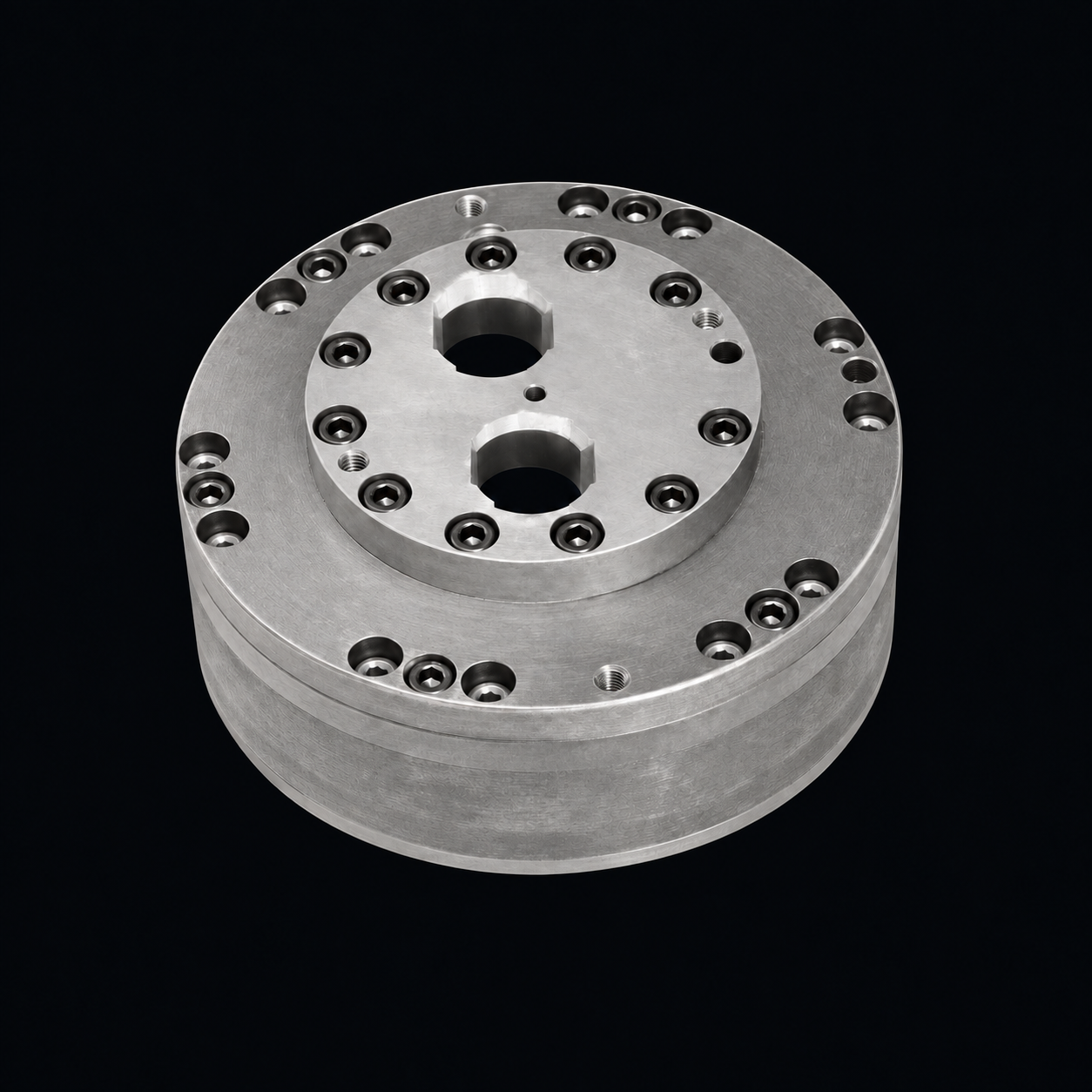
JFT24
T3Ratios 102.63 and 120.50; A2FE45–63 or A6VE55 motors.
- Output torque
- 24,000 N·m
- Weight
- approx. 105 kg
- Pilot
- φ250h8 / φ280h8
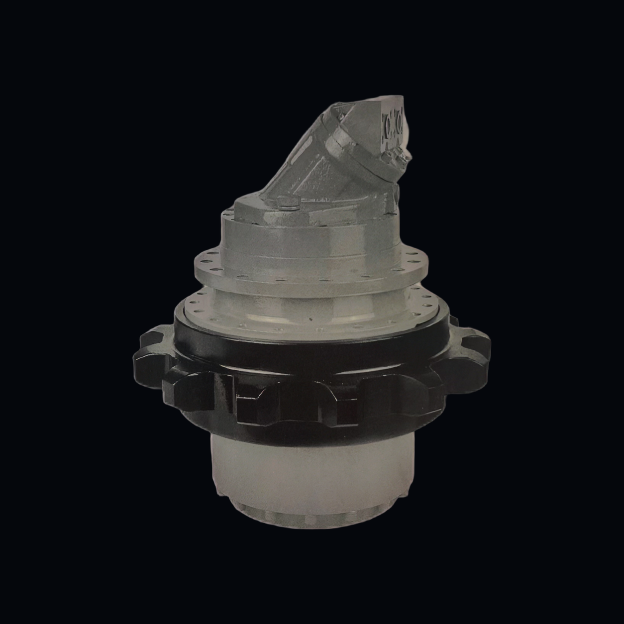
Typical JFT configuration shown. Hydraulic motor, distributor and mounting flanges are selected to suit the duty.
Wheel drives · Mainly custom-built
A rotating-housing hydrostatic travel gearbox made up of a planetary gearbox, multi-disc brake, hydraulic motor and distributor, with 2- or 3-stage planetary gearing, an integrated multi-disc parking brake and axial rotating-ring seals. It drives the travel of crawler excavators, rotary drilling rigs, roadheaders, road rollers, rail and construction vehicles; motor, ratio and seal design can be customized to the duty.
Fitted with A2FE fixed-displacement or A6VE variable-displacement motors; gearbox weight approx. 105–395 kg; output rotation is opposite to input rotation.
Technical data
Use the selection map to find the size for the output torque you need, then choose the ratio in the data table. The outline drawing, the dimensions of both mounting flanges and the matching motors are shown with each size's drawing.
Selection map
Showing all 23
Horizontal axis: output torque (N·m); vertical axis: ratio; both log scale. Each size is one column, and all ratios of a size have the same output torque.
Click any dot on the map to see its data, or enter the torque you need.
Series
| Size · ratio | Output torque (N·m) | Ratio | A2FE motors | A6VE motors | Weight (approx. kg) |
|---|---|---|---|---|---|
| JFT24 T32 ratios · 24,000 N·m · ratio 102.63–120.5 | |||||
| JFT24 T3 i=102.63 | 24,000 | 102.63 | 45, 56, 63 | 55 | 105 |
| JFT24 T3 i=120.50 | 24,000 | 120.50 | 45, 56, 63 | 55 | 105 |
| JFT36 T35 ratios · 36,000 N·m · ratio 66.96–131 | |||||
| JFT36 T3 i=66.96 | 36,000 | 66.96 | 45, 56, 63, 80, 90 | 55, 80 | 170 |
| JFT36 T3 i=79.36 | 36,000 | 79.36 | 45, 56, 63, 80, 90 | 55, 80 | 170 |
| JFT36 T3 i=100.02 | 36,000 | 100.02 | 45, 56, 63, 80, 90 | 55, 80 | 170 |
| JFT36 T3 i=116.55 | 36,000 | 116.55 | 45, 56, 63, 80, 90 | 55, 80 | 170 |
| JFT36 T3 i=131.00 | 36,000 | 131.00 | 45, 56, 63, 80, 90 | 55, 80 | 170 |
| JFT60 T35 ratios · 60,000 N·m · ratio 86.46–169.89 | |||||
| JFT60 T3 i=86.46 | 60,000 | 86.46 | 80, 90, 107, 125 | 80, 107 | 245 |
| JFT60 T3 i=105.53 | 60,000 | 105.53 | 80, 90, 107, 125 | 80, 107 | 245 |
| JFT60 T3 i=119.83 | 60,000 | 119.83 | 80, 90, 107, 125 | 80, 107 | 245 |
| JFT60 T3 i=139.86 | 60,000 | 139.86 | 80, 90, 107, 125 | 80, 107 | 245 |
| JFT60 T3 i=169.89 | 60,000 | 169.89 | 80, 90, 107, 125 | 80, 107 | 245 |
| JFT80 T35 ratios · 80,000 N·m · ratio 76.68–185.43 | |||||
| JFT80 T3 i=76.68 | 80,000 | 76.68 | 107, 125, 160, 180 | 107, 160 | 350 |
| JFT80 T3 i=98.97 | 80,000 | 98.97 | 107, 125, 160, 180 | 107, 160 | 350 |
| JFT80 T3 i=126.94 | 80,000 | 126.94 | 107, 125, 160, 180 | 107, 160 | 350 |
| JFT80 T3 i=149.92 | 80,000 | 149.92 | 107, 125, 160, 180 | 107, 160 | 350 |
| JFT80 T3 i=185.43 | 80,000 | 185.43 | 107, 125, 160, 180 | 107, 160 | 350 |
| JFT110 T36 ratios · 110,000 N·m · ratio 95.83–215 | |||||
| JFT110 T3 i=95.83 | 110,000 | 95.83 | 107, 125, 160, 180 | 107, 160 | 395 |
| JFT110 T3 i=114.83 | 110,000 | 114.83 | 107, 125, 160, 180 | 107, 160 | 395 |
| JFT110 T3 i=128.60 | 110,000 | 128.60 | 107, 125, 160, 180 | 107, 160 | 395 |
| JFT110 T3 i=147.24 | 110,000 | 147.24 | 107, 125, 160, 180 | 107, 160 | 395 |
| JFT110 T3 i=173.86 | 110,000 | 173.86 | 107, 125, 160, 180 | 107, 160 | 395 |
| JFT110 T3 i=215.00 | 110,000 | 215.00 | 107, 125, 160, 180 | 107, 160 | 395 |
No matching sizes. The search only covers models that meet the torque/speed condition; clear the condition to search all models. Tell us the torque, ratio and mounting interface you need and ask about a custom build.
Showing 2 of 23
Click a size to see its full data. Converted values; the metric values govern.
Ratings: the figure after "i=" is the total ratio; the A2FE and A6VE columns give the motor displacement sizes (full motor models are in the size details). See the model code below for the order code format.
Ratios 102.63 and 120.50; A2FE45–63 or A6VE55 motors.
Ratios 66.96–131.00; A2FE45–90 or A6VE55, 80 motors.
Ratios 86.46–169.89; A2FE80–125 or A6VE80, 107 motors.
Ratios 76.68–185.43; A2FE107–180 or A6VE107, 160 motors.
Ratios 95.83–215.00; the highest-torque size in the series.
Construction & model code
Construction, features and model code of the JFT Series.
Custom builds
The catalog models are a starting point for selection. Each item below can be designed to the torque, speed and mounting conditions of your equipment.
Dimensions in mm; left and right as shown in the drawings. Mounting dimensions are per the approved drawing.
Related products
The JFB slewing gearbox and the JSC hydraulic transmission unit also combine a motor with a planetary gearbox; for low-speed, high-torque motors, see the QJM Series.
Selection support
Send the information in the checklist and we will check it against the catalog models or assess a custom design. The product catalog and installation drawing are provided once the model and mounting interface are confirmed.