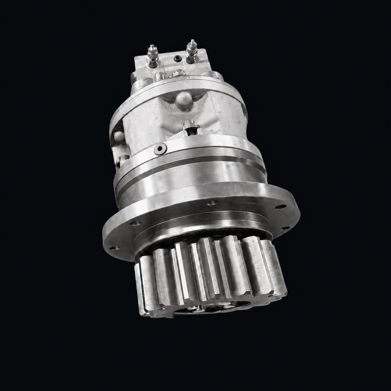
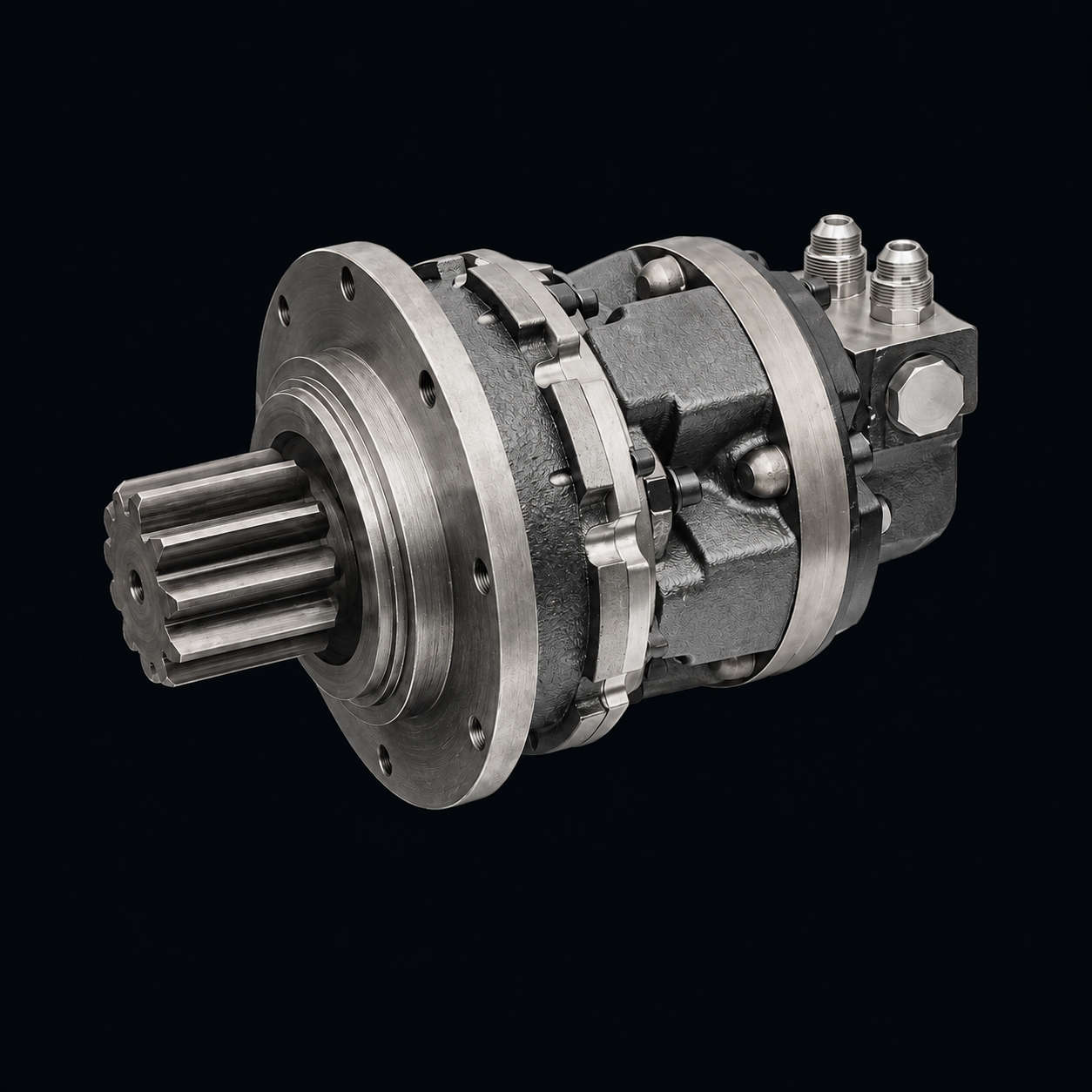
JFB17
T2 · T32-stage ratios 33–55, 3-stage 65–125; the 3-stage version is drawn with the output pinion offset 2.5 from the mounting flange.
- Excavator
- 7,700 N·m
- Crane
- 12,700 N·m
- Weight
- 130 kg
- Mounting pilot
- φ255 / φ250 h7
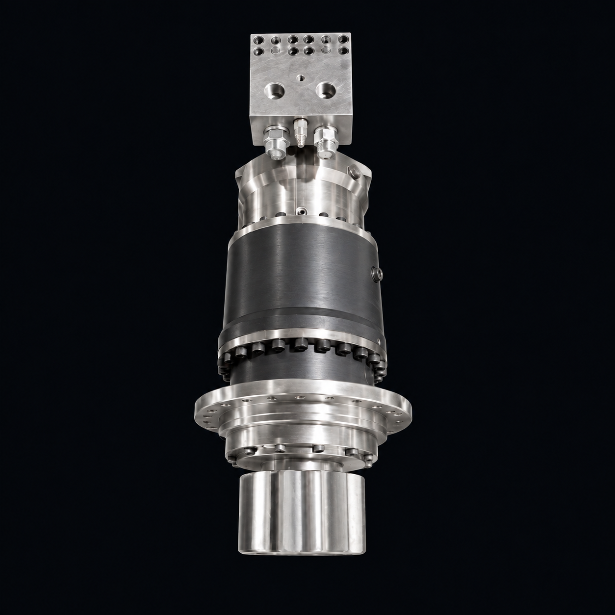
Typical JFB configuration shown. Hydraulic motor, distributor and output pinion are selected to suit the duty.
Slewing gearbox · Mainly custom-built
A slewing drive made up of a planetary gearbox, multi-disc brake, hydraulic motor and distributor. 2- or 3-stage planetary gearing keeps it compact and space-saving, with an integrated multi-disc parking brake. Used in the slewing mechanisms of excavators, cranes, marine cargo handling gear and forestry equipment; the fitted motor and the ratio can be changed to suit your requirements.
Max. output torque for crane duty 12,700–68,000 N·m; gearbox weight 130–520 kg; max. braking torque above 600–1,600 N·m. The output turns in the same direction as the input.
Technical data
Locate a size on the selection map by machine type (excavator or crane) and the max. output torque you need, then choose the ratio in the data table. Outline drawings, mounting dimensions and matching motors are shown with each size's drawing.
Selection map
Showing all 37
Horizontal axis: max. output torque (N·m) for the selected machine type; vertical axis: ratio; both log scale. All ratios of a size have the same torque and form one column. Switch between Excavator and Crane above to see both duties.
Click any dot to see its data, or enter the torque you need.
Series
| Size · ratio | Max. output torque · excavator (N·m) | Max. output torque · crane (N·m) | Ratio | Stages | Weight (kg) |
|---|---|---|---|---|---|
| JFB17 T24 ratios · excavator 7,700 / crane 12,700 N·m · ratio 33–55 | |||||
| JFB17 T2 i=33 | 7700 | 12700 | 33 | 2 | 130 |
| JFB17 T2 i=39 | 7700 | 12700 | 39 | 2 | 130 |
| JFB17 T2 i=46 | 7700 | 12700 | 46 | 2 | 130 |
| JFB17 T2 i=55 | 7700 | 12700 | 55 | 2 | 130 |
| JFB17 T35 ratios · excavator 7,700 / crane 12,700 N·m · ratio 65–125 | |||||
| JFB17 T3 i=65 | 7700 | 12700 | 65 | 3 | 130 |
| JFB17 T3 i=79 | 7700 | 12700 | 79 | 3 | 130 |
| JFB17 T3 i=89 | 7700 | 12700 | 89 | 3 | 130 |
| JFB17 T3 i=104 | 7700 | 12700 | 104 | 3 | 130 |
| JFB17 T3 i=125 | 7700 | 12700 | 125 | 3 | 130 |
| JFB24 T2/T36 ratios · excavator 10,000 / crane 17,000 N·m · ratio 79–161 | |||||
| JFB24 T2/T3 i=79 | 10000 | 17000 | 79 | 2/3 | 140 |
| JFB24 T2/T3 i=89 | 10000 | 17000 | 89 | 2/3 | 140 |
| JFB24 T2/T3 i=103 | 10000 | 17000 | 103 | 2/3 | 140 |
| JFB24 T2/T3 i=124 | 10000 | 17000 | 124 | 2/3 | 140 |
| JFB24 T2/T3 i=140 | 10000 | 17000 | 140 | 2/3 | 140 |
| JFB24 T2/T3 i=161 | 10000 | 17000 | 161 | 2/3 | 140 |
| JFB36 T22 ratios · excavator 17,000 / crane 28,000 N·m · ratio 24–29 | |||||
| JFB36 T2 i=24 | 17000 | 28000 | 24 | 2 | 190 |
| JFB36 T2 i=29 | 17000 | 28000 | 29 | 2 | 190 |
| JFB36 T35 ratios · excavator 17,000 / crane 28,000 N·m · ratio 68–132 | |||||
| JFB36 T3 i=68 | 17000 | 28000 | 68 | 3 | 210 |
| JFB36 T3 i=80 | 17000 | 28000 | 80 | 3 | 210 |
| JFB36 T3 i=101 | 17000 | 28000 | 101 | 3 | 210 |
| JFB36 T3 i=118 | 17000 | 28000 | 118 | 3 | 210 |
| JFB36 T3 i=132 | 17000 | 28000 | 132 | 3 | 210 |
| JFB60 T24 ratios · excavator 27,000 / crane 48,000 N·m · ratio 29–50 | |||||
| JFB60 T2 i=29 | 27000 | 48000 | 29 | 2 | 390 |
| JFB60 T2 i=34 | 27000 | 48000 | 34 | 2 | 390 |
| JFB60 T2 i=40 | 27000 | 48000 | 40 | 2 | 390 |
| JFB60 T2 i=50 | 27000 | 48000 | 50 | 2 | 390 |
| JFB60 T35 ratios · excavator 27,000 / crane 48,000 N·m · ratio 87–171 | |||||
| JFB60 T3 i=87 | 27000 | 48000 | 87 | 3 | 425 |
| JFB60 T3 i=107 | 27000 | 48000 | 107 | 3 | 425 |
| JFB60 T3 i=121 | 27000 | 48000 | 121 | 3 | 425 |
| JFB60 T3 i=141 | 27000 | 48000 | 141 | 3 | 425 |
| JFB60 T3 i=171 | 27000 | 48000 | 171 | 3 | 425 |
| JFB80 T36 ratios · excavator 38,000 / crane 68,000 N·m · ratio 63–186 | |||||
| JFB80 T3 i=63 | 38000 | 68000 | 63 | 3 | 520 |
| JFB80 T3 i=78 | 38000 | 68000 | 78 | 3 | 520 |
| JFB80 T3 i=100 | 38000 | 68000 | 100 | 3 | 520 |
| JFB80 T3 i=128 | 38000 | 68000 | 128 | 3 | 520 |
| JFB80 T3 i=151 | 38000 | 68000 | 151 | 3 | 520 |
| JFB80 T3 i=186 | 38000 | 68000 | 186 | 3 | 520 |
No matching sizes. The search only covers models that meet the torque condition; clear the condition to search all models. Tell us the torque, ratio and mounting interface you need and ask about a custom build.
Showing 4 of 37
Click a size to see its full data. Converted values; the metric values govern.
Ratings: max. output torque is given separately for excavator and crane duty and is the same for all ratios of a size. The number after "i=" is the ratio; the order code states the actual total ratio and the motor model (see the model code below). JFB24 T2 and T3 share one set of data.
2-stage ratios 33–55, 3-stage 65–125; the 3-stage version is drawn with the output pinion offset 2.5 from the mounting flange.
Ratios 79–161; mounting dimensions as drawn are the same as JFB17 T2, mounting holes 16-φ17.5.
2-stage ratios 24–29, 3-stage 68–132; fits A2F and A2FE series motors 45–125.
2-stage ratios 29–50, 3-stage 87–171; 2-stage max. braking torque above 1,600 N·m.
3-stage ratios 63–186, the highest-torque size in the series; fits A2F and A2FE series motors 80–200.
Construction & model code
Components, features and model code of the JFB Series.
Custom builds
The catalog models are a starting point for selection. Each item below can be designed to the torque, speed and mounting conditions of your equipment.
Dimensions in mm; "—" means not dimensioned. Overall length is a reference dimension, measured to the flange upper face for JFB17 T3 and to the pinion end for the others. Mounting dimensions are per the approved drawing.
Related products
Other slewing drives include the JSH slewing drive (JNM motor, planetary gearbox and output pinion in one unit) and the JSC hydraulic transmission unit.
Selection support
Send the information in the checklist and we will check it against the catalog models or assess a custom design. The product catalog and installation drawing are provided once the model and mounting interface are confirmed.