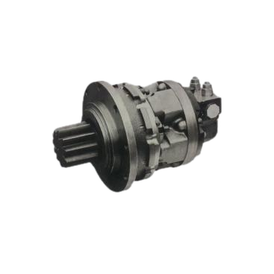
Why hydraulic drive fits plate rolling
The typical load is slow, heavy and sometimes impacted. During pre-bending and roundness correction, rollers may reverse frequently. A hydraulic motor with appropriate valves and power unit supports reversing, stepless speed adjustment and controlled torque output.
- High torque at low speed
- Forward and reverse control
- Relief-valve overload protection
- Integration with planetary reduction, brake and manifold
- Flexible packaging for different machine sizes
Main system components
A complete system commonly includes a hydraulic power unit, motor, planetary gearbox, valve block, reservoir, filters, cooler, pipework and controls. Pump flow establishes the motor speed range; pressure supports load torque; cooling capacity must follow the real continuous duty.
Motor, gearbox and valve functions
Low-speed high-torque motors, orbital motors or radial piston motors can be considered according to machine size and duty. Large machines often add a gearbox to reduce speed and increase output torque. Directional valves control reversing, flow or proportional valves adjust speed, and relief valves protect pressure. Balance valves, brake valves or pilot-operated checks may be required for controlled holding.
Key selection parameters
Required torque depends on plate thickness, plate width, material yield strength, roller diameter and transmission efficiency. Confirm minimum, normal and maximum speed, and separate normal working pressure from short peak pressure. Motor displacement, pump flow and gearbox ratio must be matched together.
Large rollers may need a brake, a motor-gearbox-brake assembly or an appropriate holding circuit while the rollers remain loaded.
Common operating problems
Roller lacks power
Check system pressure, relief setting, pump wear, motor leakage and mechanical resistance. High pressure with no movement points toward load or transmission resistance; pressure that cannot rise points toward pump, valve or leakage problems.
Unstable speed
Check aeration, pump-flow stability, valve sticking, low-speed behavior, oil level, suction sealing and filter condition.
High oil temperature
Look for prolonged relief flow, internal leakage, insufficient cooling and excessive line loss.
Reversing impact
Slow the directional transition, consider proportional control or buffering, and review brake-valve settings for high-inertia rollers.
Maintenance checklist
- Replace oil and filters on the approved schedule
- Keep the motor drain line open and unrestricted
- Inspect coupling, gearbox, bolts and bearings
- Monitor oil temperature and abnormal noise
- Run unloaded at low speed after maintenance
- Investigate crawling and leakage early
Information for a system review
Send plate thickness, plate width, material, roller diameter, output torque or existing drive data, target speed, working pressure, duty cycle and installation requirements. JST can review the motor, gearbox, brake and valve circuit as a system.
Technical information is provided for preliminary selection. Confirm the selected model, installation and application requirements before ordering.