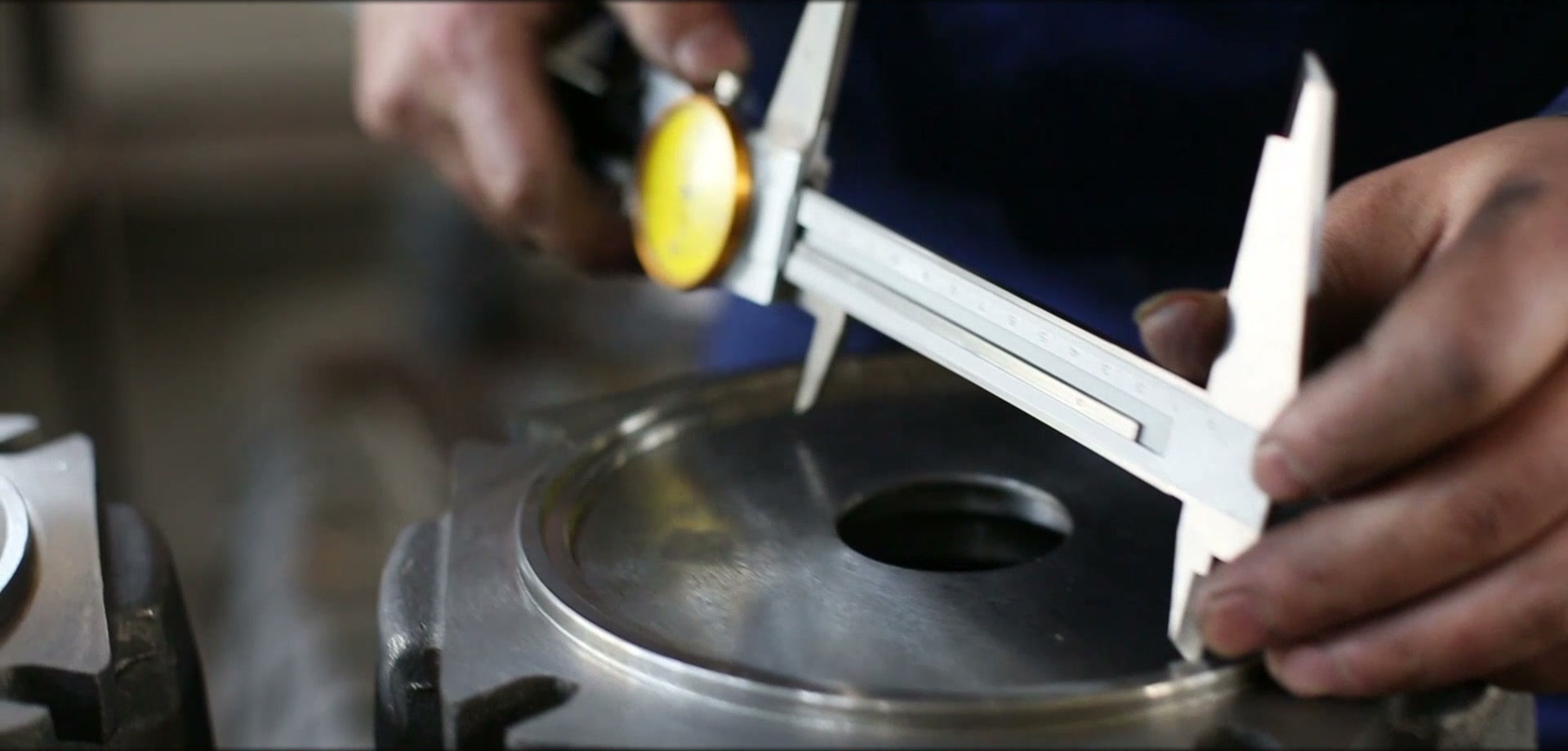
Record the mechanical interface
- Flange pilot, bolt-circle diameter, hole quantity and hole size
- Shaft diameter, spline or key dimensions and usable shaft length
- Overall length, housing diameter and nearby interference points
- Permitted shaft load and coupling arrangement
Record the hydraulic interface
- Main port thread, position and flow direction
- Case-drain requirement and drain-port location
- Working pressure, peak pressure, return pressure and available flow
- Brake-release or pilot-pressure requirement
Describe how the machine actually works
State the driven load, operating speed range, starts per hour, reversing frequency, duty cycle, ambient conditions and failure mode of the old unit. This explains requirements that a drawing cannot show.
Approve with a comparison drawing
Before ordering, compare the proposed motor installation drawing against the machine interface. Confirm coupling engagement, port access, rotation direction and service clearance. Final replacement approval belongs to the machine designer or responsible engineer.
Engineering note
This guide supports preliminary discussion. Final selection must be confirmed from the specific model data, hydraulic circuit, installation drawing and machine safety requirements.